Twist lock plugs are essential for securing power connections where safety is a top priority. They must be twisted into a compatible receptacle to ensure a stable connection. This is why technicians often use them for portable generators, production gear, and heavy-duty machinery to reduce the risk of accidental disconnections.
L6-20 Receptacle
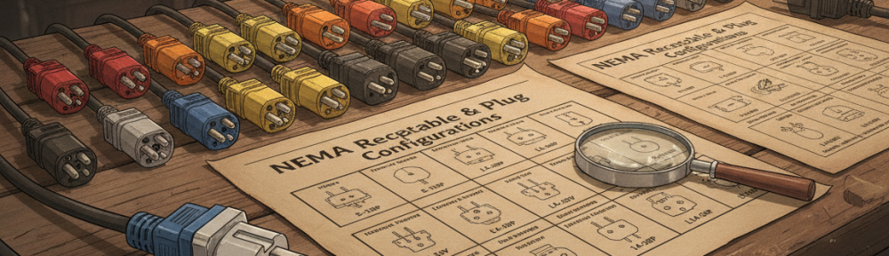
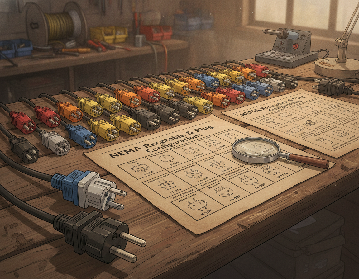
Reputable makers including Kellems provide twist-lock components with NEMA stamps and UL-style safety listings such as UL 498. A Nema Chart Twist Lock reference helps users compare voltage, amperage, blade layout, and whether the device belongs to a locking or non-locking family. That distinction matters because using the wrong adapter, plug, or receptacle can create shock hazards.
This guide is designed to help you in understanding Nema Chart Twist Lock charts, focusing on common types like L5, L6, and L14 families. Subsequent sections will provide insights into the L6-20 and an L6-20 Plug Wiring Diagram. With the right chart-reading approach, you can select compatible parts and plan safer installations without relying on guesswork.
- Twist lock plugs use a rotate-to-lock action for secure connections.
- NEMA twist lock charts identify voltage and amperage for proper selection.
- Trust recognized manufacturers like Legrand, Eaton, and Kellems and verify UL listings.
- Avoid mismatched adapters; use properly paired locking plugs and receptacles.
- Section topics include L6-20 connector basics and an L6-20 Plug Wiring Diagram.
Why Twist Lock Plugs Matter For Electrical Safety
Twist-lock plugs are heavy-duty electrical connectors with curved contact blades that turn into locking receptacle grooves. This design, known as Turnlok by Hubbell and Leviton, creates a locked-in connection. That lock helps the plug resist pullout caused by vibration, movement, cord tension, or accidental bumps.
After the plug is inserted, a short turn seats it into the locking position. This action seats the blades into matching grooves, ensuring consistent conductivity. By reducing partial withdrawal and loose fit, the design helps limit arcing, exposed conductors, and intermittent power problems.
These connectors are frequently specified in construction sites, manufacturing floors, HVAC installations, and data centers. They are also found in portable generators, stage and studio rigs, hospital equipment, and refrigeration units. Because these locations may involve vibration, movement, or critical loads, dependable power retention becomes especially important.
Professional electricians prefer locking devices in high-risk environments. A Nema Chart Twist Lock reference and an L6-20 Plug Wiring Diagram help match the correct plug, receptacle, voltage, and wiring layout. Together, these references reduce the chance of mismatched voltage, incorrect amperage, or improper grounding.
Twist-lock connectors provide practical safety benefits in many work environments. By staying locked in place, they lower the risk of accidental unplugging, arcing, exposed contacts, shock, and fire hazards. Using properly rated, UL-listed components and following the L6-20 Plug Wiring Diagram improves compliance with the National Electrical Code.
| Design Feature | Why This Matters | Frequent Application |
|---|---|---|
| Curved blade with locking groove | Creates secure mechanical locking to resist pullout | Generator cords, stage rigs, HVAC equipment |
| Ground-first engagement | Ensures grounding before power contacts mate | Medical equipment, data centers |
| NEMA markings and UL listings | Confirms correct voltage, amperage, and safety standards | Commercial wiring and industrial equipment |
| NEMA compatibility charts | Reduces the chance of mismatched components | Maintenance crews and installers |
NEMA Chart Basics For Twist Lock Connectors
Technicians and electricians need to understand NEMA configurations so plugs, receptacles, voltages, and amperages are correctly matched. A Nema Chart Twist Lock section identifies the voltage class, current rating, blade arrangement, and locking style. Reading these details correctly helps prevent unsafe pairings, equipment damage, overheating, and shock hazards.
Reading NEMA Codes And Letter Markings
A NEMA designation usually combines a configuration number, a dash, and an amperage rating. For example, 5-15 points to a 125V configuration rated for 15 amps. The prefix L denotes locking types, like L5-20P, which is a locking plug. Letters P and R mean plug and receptacle, respectively. Most charts also include common voltage classes such as 125V, 250V, 277V, 125/250V, and 480V so users can avoid mismatching equipment.
How NEMA Charts Separate Locking From Non-Locking Devices
NEMA charts usually divide straight-blade and locking connectors into separate sections. Examples of non-locking devices include 5-15, 6-20, and 14-30 or 14-50 configurations. Locking families such as L5, L6, and L14 are marked with an L prefix and are commonly chosen for outdoor, industrial, or vibration-prone locations. Straight-blade non-locking devices are more common in homes and light commercial work where locking retention is not required.
Useful Tips For Reading NEMA Charts
- Confirm P-to-R compatibility before energizing any device.
- Match voltage and ampacity without substitution; a L6 20 Plug must pair with the correct receptacle rated for the same voltage and amps.
- Check pin count and configuration: three-wire versus four-wire and whether two hot conductors or hot/neutral/ground are used.
- Use blade design and orientation indicators on the chart to avoid cross-connection between incompatible voltage or amperage devices.
Nema Chart Twist Lock: Popular Locking Families And Applications
Twist lock connectors are valuable for avoiding accidental disconnections in environments with vibration or movement. A Nema Chart Twist Lock reference quickly shows connector families, voltage ratings, amperage ratings, and practical uses. By comparing the chart before installation, users can choose the correct device and avoid mismating that may cause downtime, overheating, or unsafe operation.
Below, we review typical families, their ratings, and ideal uses. L5 devices are commonly used on 125V circuits and are available in ratings such as 15A and 20A. L5-15 and L5-20 are often selected in stage lighting and portable power distribution, where cords must remain connected despite stress.
L6 types serve 250V single-phase circuits, ideal for motors and HVAC systems. L6-20 and L6-30 devices are often chosen for industrial machinery, refrigeration equipment, and other 250V loads. The twist-lock action helps prevent accidental disconnection while the equipment is operating.
L14 connectors are four-wire 125/250V devices commonly associated with generators, transfer switches, and temporary power. With two hots, a neutral, and a ground, L14-20 and L14-30 connectors are practical for generator outputs, transfer panels, and jobsite power.
Some higher-amperage locking receptacles, including L530R and L630R styles, use distinct configurations so incompatible voltages are not easily mixed. When 30A power is required, selecting the correct connector helps maintain safe operation and reduces the risk of misconnection.
Practical applications extend from stage production to construction and facility maintenance. For portable lighting and 125V loads, L5-15 or L5-20 may be appropriate when ratings match. For 250V motors or HVAC equipment, L6-20 and L6-30 are commonly reviewed. For generator and transfer-switch arrangements, L14-20 or L14-30 may be the correct family. When a 30A four-wire feed is necessary, L530R or L630R is the best choice to avoid mismating.
| Locking Connector | Rated Voltage | Current Rating | Frequent Uses |
|---|---|---|---|
| L5-15 locking device | 125V class | 15A | Portable 125V devices, stage lights, small tools |
| L5-20 | 125-volt | 20-amp rating | Temporary power distribution, equipment with vibration |
| L6-20 | 250V class | 20-amp rating | HVAC units, industrial motors, machine tools |
| L6-30 | 250V class | 30-amp rating | Heavier machinery, larger HVAC, shop equipment |
| L14-20 | 125/250-volt | 20 amps | Portable generators, transfer switches, jobsite power |
| L14-30 connector | 125/250V class | 30-amp rating | Generator outputs, larger transfer panels, RV shore power |
| L530R receptacle | 125V class | 30 amps | 125V 30A circuits requiring correct locking configuration |
| L630R receptacle | 250-volt | 30 amps | 250V 30A circuits where mismating must be avoided |
Focus On L6-20 Plug Wiring Diagram And L6-20 Specifics
The L6-20 locking connector is a 250-volt, 20-amp option used in industrial and HVAC settings. The standard layout uses two hot conductors plus an equipment grounding conductor. The blade configuration is intentionally different from 125V devices, helping prevent wrong connections when the Nema Chart Twist Lock is followed.
Key L6-20 plug and receptacle details
The L6 20 Plug uses a compact, twist-lock design with two hot blades and a single pin for ground. Common construction includes brass contacts and molded thermoset or industrial-grade housings from brands such as Leviton or Hubbell. Always compare the P and R designations on a Nema Chart Twist Lock so the plug and receptacle are correctly paired.
Best practices for L6-20 wiring
Select the correct conductor size for a 20A circuit, commonly 12 AWG copper, or follow NEC sizing for specific run length and temperature. Securely tighten terminals to the manufacturer’s recommended torque and use cord grips or strain reliefs to prevent conductor pull-out.
Before energizing the circuit, verify grounding continuity and correct conductor placement. Use a calibrated multimeter and a continuity tester to confirm hot-to-hot and ground connections. Clearly label the receptacle area with voltage, amperage, and circuit information so future users can identify it safely.
Example notes for an L6-20 Plug Wiring Diagram
An L6-20 Plug Wiring Diagram should show two hot conductors and a separate equipment grounding conductor. A neutral is not part of the typical L6-20 wiring layout. The diagram should also include terminal labels, conductor colors where applicable, and torque values for installers.
| Category | Technical Detail | Installation Guidance |
|---|---|---|
| Rated voltage | 250-volt | Verify against the equipment nameplate and Nema Chart Twist Lock |
| Ampacity | 20-amp service | Use 12 AWG copper or NEC-compliant conductor sizing |
| Conductor arrangement | Two hots, one ground | Use hot-hot-ground unless equipment documentation says otherwise |
| Typical applications | 250V industrial and HVAC loads | Confirm the equipment is intended for an L6 20 Plug |
| Materials | Conductive contacts with durable housing | Use listed parts from recognized manufacturers |
| Final checks | Continuity testing and torque verification | Test before energizing and document results |
A Closer Look At L6 20 Plug, L6-20 Receptacle, And L6-20R Wiring
To avoid failures in the field, it is important to understand the parts, wiring steps, and inspection points used with L6-20 devices. This section breaks down the anatomy of each part, outlines the installation process for an L6-20R receptacle, and highlights essential inspection and testing points. For best results, use NEMA-stamped and UL-listed products from reliable manufacturers such as Legrand, Eaton, and Kellems.
Materials And Construction Of L6-20 Devices
Device housings may be made from thermoplastic or metal to suit indoor, industrial, or harsh environments. Curved blades and strong contacts help maintain firm engagement while reducing wear. Cord grips and strain-relief features reduce conductor pullout.
Contact materials are often finished with low-resistance plating for low resistance. Available styles may include weatherproof, flush-mount, surface-mount, and industrial designs for different environments. Manufacturers such as Legrand and Eaton typically provide specifications, listing details, and installation data for each device.
Installing And Wiring An L6-20R Receptacle
Always turn off the power at the breaker before starting any work. Ensure the box is mounted correctly using the appropriate hardware for the surface. The enclosure should match the installation environment.
Conductors should be stripped only to the length specified in the device instructions. Terminal screws should be tightened to the listed torque value in the manufacturer’s documentation. Proper cord grips and cable clamps should be used so pulling force is not transferred to the terminals.
After installation, label the circuit and confirm that the breaker rating matches the L6 20 Plug, receptacle, and branch-circuit ampacity. For permanent installations or higher-power work, follow the NEC and use a licensed electrician where required.
Testing And Inspection After L6-20 Installation
Before energizing, check conductor continuity and verify the hot conductors and grounding path with a multimeter. Perform insulation resistance testing when available to confirm no shorts or moisture paths exist.
Verify grounding by measuring resistance to a known good ground. A matching L6 20 Plug should insert, twist, and lock firmly without looseness or excessive force.
During reinspection, use the manufacturer’s torque values and applicable UL guidance. If a device fails testing, shows heat damage, or has damaged terminals, replace it rather than attempting unsafe field repair.
| Inspection Item | Recommended Practice | Why It Matters |
|---|---|---|
| L6-20 Plug Wiring Diagram | Match the diagram precisely and label conductors clearly | Helps installers avoid wrong conductor placement |
| L6-20 Receptacle mounting | Use proper box, secure mounting screws, and gaskets for outdoor installs | Maintains weatherproof seal and prevents mechanical stress on terminals |
| L6-20R Wiring checks | Check continuity, insulation condition, and ground path | Helps identify faults before energizing equipment |
| Terminal termination | Follow torque specs and terminate stranded wire properly | Reduces heat buildup and prevents loosening over time |
| Device selection | Choose UL-listed parts from Legrand, Eaton, or Kellems | Ensures traceable quality and compatibility with L6 20 Plug standards |
Safety Warnings And Common Twist Lock Installation Errors
Many twist-lock failures start with simple mistakes such as wrong ratings, poor termination, or mismatched devices. Reading the NEMA markings and applicable wiring rules is essential before connecting equipment. Using the Nema Chart Twist Lock correctly helps avoid mismatched plugs and receptacles that may overheat, arc, or shock users. If unsure, always consult a licensed electrician before proceeding.
Why Twist Lock Adapters Are Discouraged
Twist lock adapters seem convenient but often fail to fully seat or lock. This incomplete connection raises resistance and heat at the contact points.
Many twist lock adapters do not have UL listing or are underspecified for the advertised amperage. Reputable manufacturers like Hubbell and Legrand rarely offer field adapters for locking devices. Using an unlisted adapter significantly increases the risk of melting and fire.
Frequent Wiring And Selection Errors
Common mistakes include incorrect current rating and voltage. Plugging a 20A load into a 15A circuit can overload conductors and devices.
Incorrect conductor size and loose terminal screws are also common causes of failure. A poor termination or a backstabbed conductor creates a hot spot that can char insulation.
Another common mistake is ignoring the P and R markings that identify plugs and receptacles. Mixing NEMA families, modifying blades, or ignoring the Nema Chart Twist Lock can create dangerous and non-compliant setups.
Regulatory And Professional Guidance
The National Electrical Code governs branch-circuit wiring and device ratings. Use the NEC sections that apply to receptacles, cord-connected equipment, grounding, and overcurrent protection. Select UL-listed components and NEMA-stamped devices so ratings and configurations can be verified.
For L6-20R Wiring and other locking receptacles, hire a licensed electrician for installation and testing. A permit and inspection may be required by local authorities having jurisdiction.
Critical safety reminders: avoid jury-rigged adapters, stay within device ratings, and verify all terminations and tests before putting equipment into service.
Selecting Twist Lock Connectors And Reliable Suppliers
To choose the correct twist-lock product, first match the NEMA code to the equipment voltage, amp rating, and conductor count. The installation environment also matters, especially whether the device will be indoors, outdoors, wet, dusty, or exposed to vibration. Weather resistance, corrosion resistance, and vibration performance should be part of the selection process. Also, check the cord length, strain relief, and terminal materials before making a purchase.
Selection Checklist
Here’s a quick checklist to simplify your options. Ensure the NEMA stamping and UL listing match. For equipment needing a 240V or 250V, 20A locking connection, compare the device against an L6-20 Plug Wiring Diagram. For wet, salty, coastal, or corrosive locations, choose materials and housings designed to resist corrosion.
- Confirm NEMA code and configuration against a Nema Chart Twist Lock.
- Verify voltage, amperage, and wire count compatibility.
- Choose weatherproof or indoor-rated housings as needed.
- Check strain relief, cord rating, and terminal material.
- Cross-check with an L6-20 Plug Wiring Diagram when selecting L6 20 Plug and L6-20 Receptacle parts.
Certifications And Brands To Look For
Stick with established manufacturers like Legrand, Eaton, and Hubbell for reliable components. A genuine device should show clear NEMA identification and appropriate UL listing information. Authentic, listed products are easier to verify and generally support inspections better than unbranded or unverified alternatives.
| Manufacturer | Product Strength | Common Certifications |
|---|---|---|
| Legrand | Wide product range, durable housings | Listed products with NEMA identification |
| Eaton connectors | Industrial-grade connectors and durable designs | UL listing and CSA where applicable |
| Hubbell | Rugged devices and weather-resistant options | UL listed, NEMA stamping |
Where To Purchase
Purchase twist-lock devices from authorized electrical distributors or verified online suppliers to reduce the risk of counterfeit parts. Installation Parts Supply can provide connector options along with useful product details for comparison. Use manufacturer catalogs and NEMA charts to verify compatibility before purchasing.
- Compare product specs to a Nema Chart Twist Lock entry.
- Confirm UL listing and manufacturer warranty.
- Purchase from an authorized dealer or known distributor.
Twist Lock Safety Conclusion
When planning or verifying installations, use the Nema Chart Twist Lock as your guide. An L6 20 Plug should only be connected to the correct matching receptacle with the same NEMA locking configuration. Before energizing equipment, confirm voltage, amperage, conductor count, and blade layout against official chart data.
For L6-20 installations, adhere to a detailed L6-20 Plug Wiring Diagram and use proper L6-20R Wiring methods. Locking connectors are essential in industrial and commercial settings, preventing accidental disconnections. They are especially useful where vibration, movement, or frequent use is expected. Never use jury-rigged adapters or uncertified parts, as they compromise safety.
Opt for UL-listed, NEMA-stamped devices from trusted suppliers and authorized distributors for consistent performance. For permanent or high-power installations, hire a licensed electrician and follow the National Electrical Code. Proper planning, correct parts, and professional installation help keep systems are safe and reliable.